
 English
 中文
中文 العربية
 español

Key takeaways
-
Dual-loop CDUs protect IT coolant quality and reduce risk by isolating facility water through a plate heat exchanger.
-
The most consequential control variables are secondary supply temperature, dew point margin, approach temperature, differential pressure (DP), flow, and ΔT.
-
“Efficiency gains” come from physics, not slogans: higher coolant temperatures can reduce chiller lift and expand economizer hours—as long as dew point margin and IT inlet limits are protected.
-
Redundancy is only real when switchover is tested under load and alarms are wired into a safe, predictable shutdown sequence.
Introduction
AI and HPC racks are pushing beyond what air can move economically. Once you’re planning 20–30 kW racks (and certainly beyond), the limiting factors often shift from “can we cool it?” to “can we cool it predictably without blowing up energy, water, or reliability margins?” Liquid cooling—and the Coolant Distribution Unit (CDU) at the center of it—turns into a controls problem: you win or lose on Coolant Distribution Unit controls.
A CDU is more than a pump skid. It’s where you translate facility-side constraints (chilled water availability, economizer windows, treatment chemistry, maintenance practices) into IT-side requirements (stable inlet temperature, stable DP, clean fluid, predictable flow at each rack).
“Dual-loop” heat exchange is the key enabler: facility water stays on one side, the technology cooling system (the IT coolant loop) stays on the other, and a plate heat exchanger transfers heat across the boundary. That isolation improves safety (contamination and chemistry stay contained) and lets you run the IT loop at temperatures and control behaviors that optimize total plant efficiency.
Smart controls are what turn that architecture into lower PUE/WUE. By resetting temperature and pressure targets based on real demand—while maintaining a hard dew point margin—you can reduce chiller lift, increase economizer hours, and avoid over-pumping.
Thermal logic of the CDU
Dual-loop isolation and heat exchanger approach
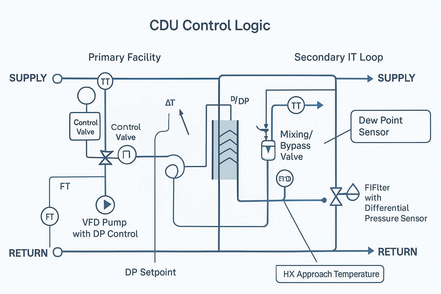
A dual-loop CDU typically has:
-
Primary (facility) loop: water from a chiller plant, cooling tower + heat exchanger, dry cooler, or other heat rejection.
-
Secondary (IT) loop: a controlled fluid circuit feeding cold plates, in-rack manifolds, or immersion distribution.
-
Plate heat exchanger (HX): transfers heat with a measurable “approach” (the temperature difference between hot-side and cold-side leaving temperatures, depending on how you define it).
The controls objective is simple to state and hard to execute: maintain IT-side supply conditions while letting the facility side run as “warm” as it safely can. The closer you can run to ambient (or to an economizer mode) without violating IT limits, the more you reduce mechanical cooling work.
A practical way to think about it: the plate HX is your gearbox. The controls decide which “gear” you’re in (warm-water/economizer-friendly vs colder, mechanically-cooled) based on constraints, not comfort.
Setpoints: supply, return, and dew point margin
On the secondary loop, three temperatures matter operationally:
-
Secondary supply temperature (to IT): the number your IT equipment actually “feels.”
-
Secondary return temperature (from IT): indicates load and heat pickup.
-
Room (or local) dew point: determines condensation risk on any surface below it.
Dew point control isn’t optional in mixed environments. Even if cold plates are insulated, manifolds, quick disconnects, and service access points can become condensation surfaces.
A common operator rule is to maintain a dew point margin—keep secondary supply temperature at least ~2°C above the measured dew point (site policy varies). This aligns with widely used condensation-avoidance principles: keep the cold surface temperature above the ambient dew point so moisture doesn’t condense.
Warning: If you reset secondary supply temperature downward for “extra headroom” without tracking dew point, you can trade a small thermal benefit for a big reliability risk.
Flow, delta-T, and differential pressure fundamentals
Flow control is where energy efficiency often gets accidentally destroyed.
-
ΔT (delta-T) on the secondary loop is your “heat carried per unit flow.” Higher ΔT generally means you’re moving the same heat with less flow—reducing pump power—until you hit IT thermal limits or cold plate design constraints.
-
Differential pressure (DP) is what ensures each branch (rack/manifold) can pull its required flow without starving. This is where CDU differential pressure control lives in practice.
-
Pump power rises quickly with speed and flow; DP setpoint selection (and how you reset it) matters.
In practice:
-
Use DP as the control target (at a representative point in the distribution) and let flow be the result.
-
Use ΔT trending to detect when you’re over-pumping (low ΔT at high flow) or under-flowing (high ΔT plus rising component temperatures).
Design guidance for liquid-cooled data centers also emphasizes maintainability: rack isolation valves and dripless quick disconnects support servicing without draining the full loop, and pressure monitoring at nodes helps leak detection and flow integrity. That’s echoed in CSE Magazine’s liquid-cooling piping guidance on isolation and leak-risk reduction (see CSE Magazine’s guidance on piping systems for liquid cooling).
Controls that cut PUE (Coolant Distribution Unit controls)
Valve and pump modulation sequences
A controls-first CDU sequence typically separates two jobs:
-
Temperature control (thermal) — keep secondary supply at setpoint while respecting dew point margin and IT limits.
-
Pressure/flow control (hydraulic) — maintain stable DP at the distribution so valves/branches behave predictably.
A practical modulation sequence looks like this:
-
Secondary pumps (VFD) track a DP setpoint at the end of a header or at the most remote manifold (worst-case). When load drops, DP reset can reduce pump speed rather than forcing excess flow through bypass.
-
Mixing/bypass valve(s) (depending on design) stabilize secondary supply temperature when facility-side temperature or load swings. The goal is to avoid “hunting” that creates temperature noise at cold plates.
-
Primary-side control valve (or pump control) manages facility-water flow through the HX to meet the secondary-side thermal demand without over-driving the facility loop.
The efficiency lever here is not “run everything slower.” It’s run only as hard as needed to satisfy constraints:
-
Keep DP just high enough to meet the worst-case rack.
-
Keep secondary supply just high enough to meet IT needs (and just high enough to maintain dew point margin).
-
Keep approach temperature reasonable by ensuring the HX is neither starved nor flooded.
Sensing, PLC logic, and KPI targets
CDU efficiency lives or dies on instrumentation quality and control stability.
Minimum sensing that actually supports optimization:
-
Secondary supply and return temperatures (with validated sensor placement)
-
Space dew point (or local dew point near manifolds) for dew point margin control
-
DP at a representative control point (plus pump suction/discharge pressure for diagnostics)
-
Flow (loop or branch) where practical
-
Filter differential pressure (to trigger maintenance before restrictions cause hydraulic instability)
PLC logic should separate normal optimization from protection interlocks:
-
Protection: dew point margin violation, low flow to critical branches, leak detection, pump fault, high temperature.
-
Optimization: DP reset, temperature reset (warm-water strategy), staging lead/lag pumps, deadbands to prevent hunting.
KPI targets worth trending (because they’re actionable):
-
Dew point margin (°C)
-
Secondary supply temperature stability (±°C)
-
DP stability (kPa)
-
ΔT (°C) at steady load
-
Pump speed (%), valve position (%), and how often they “hunt”
-
Economizer hours (% of time in free cooling) and chiller lift proxy (where available)
For operational best practices around CDU monitoring (temperature/pressure/flow/filtration) and maintaining secondary supply above dew point, see Vertiv’s overview on installing and managing CDUs.
Warm-water strategies and economizer hours
Warm-water operation is the cleanest path to lower cooling energy—because it changes the upstream system’s job.
If you can run the secondary loop warmer (within IT inlet limits and dew point margin), you can:
-
Reduce or eliminate mechanical cooling hours (more time on dry coolers/economizers)
-
Reduce chiller lift when chillers run
-
Operate cooling towers more efficiently (depending on climate and approach)
A controls-safe warm-water liquid cooling strategy is a bounded reset:
-
Temperature reset upward when load is stable and dew point margin is healthy.
-
Clamp the reset based on (a) dew point margin target, (b) IT vendor inlet limits, and (c) HX approach constraints.
-
Step changes, not aggressive ramps, to avoid thermal transients that trip IT protection.
Think of it as “maximize economizer eligibility without flirting with condensation or inlet excursions.”
Deployment patterns for AI/HPC
Capacities, pressure, and per-rack flow budgeting
AI/HPC deployment planning is mostly budgeting:
-
Capacity (kW): CDU and HX sizing must cover peak heat load with margin.
-
Pressure (DP): worst-case rack/manifold pressure drop + distribution losses determine DP setpoint headroom.
-
Per-rack flow: derive from heat load and allowable ΔT, then verify against cold plate/manifold vendor limits.
A practical approach:
-
Start with target rack kW and expected heat-to-liquid ratio.
-
Choose a target ΔT band that’s realistic for your hardware.
-
Compute required flow and map it to manifold/rack constraints.
-
Add distribution losses and choose a DP control point that reflects the worst-case path.
If you treat DP like an afterthought, you’ll end up compensating with pump speed—and that shows up directly in energy and control instability.
Redundancy topologies and automatic switchover
For operators, redundancy isn’t a topology diagram—it’s a tested behavior.
Common patterns:
-
N+1 pumps inside a CDU: lead/lag with automatic failover.
-
N+1 CDUs on shared headers: one CDU can carry load if another is isolated (within capacity limits).
-
Row-level or pod-level redundancy: reduces blast radius and supports maintenance windows.
What to actually test (and document):
-
Pump failover: confirm DP and supply temperature stay within bounds during switchover (i.e., validate redundancy switchover under load).
-
Valve fail position: confirm a stuck valve doesn’t starve a critical branch.
-
Sensor failure behavior: confirm the PLC moves to a safe default and alarms clearly.
Reference pod layouts and scaling on headers
A scalable layout usually looks like parallel CDUs feeding shared supply/return headers, with rack-level isolation valves and N+1 pump capacity where it matters.
When discussing integrated interoperability and service: Coolnet can support CDU integration with monitoring and lifecycle service across mixed-vendor data center infrastructure.
Integration and architectures
Liquid-to-liquid vs liquid-to-air/refrigerant
Most AI/HPC deployments prefer liquid-to-liquid CDUs because they cleanly separate:
-
Facility heat rejection choices (chiller, tower, dry cooler)
-
IT loop requirements (cleanliness, stable temperature, specific coolant chemistry)
Liquid-to-air or refrigerant-based approaches can work, but they change failure modes and maintenance patterns. The key is to preserve controllability: stable secondary supply temperature and stable DP at the distribution.
Facility water interfaces and heat reuse opportunities
The facility side is where you can harvest system-level wins:
-
Temperature reset on the IT loop can be coordinated with chilled-water reset upstream.
-
If your site has adjacent loads (district heating, process heat, building reheat), warm-water loops can make heat reuse more practical.
Heat reuse is never “free”—it’s a controls and contracts problem as much as a thermodynamics one. But CDUs are the interface point where you can make reuse feasible without exposing IT to facility variability.
Water quality, filtration, and maintenance windows
Water quality is a controls topic because fouling and corrosion show up as:
-
rising HX approach temperature
-
rising pump speed to maintain DP
-
unstable flows at branches
Operational best practices emphasize filtration on the secondary loop to protect cold plates and keep long-term performance stable; for example, Vertiv highlights CDU monitoring and filtration as part of installation and ongoing management.
From a maintainability standpoint, piping design guidance stresses isolation valves and serviceable connections so you can plan maintenance windows without draining the entire system.
Reliability and risk controls
Common failure modes and mitigations
Failure modes you can design-and-control for:
-
Loss of flow (pump failure, clogged filter, valve stuck): mitigate with redundancy, DP alarms, and filtered, logged trends.
-
Temperature excursion (facility-side upset, control hunting): mitigate with deadbands, staged resets, and validated sensor placement.
-
Condensation risk (dew point rises, supply setpoint drops): mitigate with dew point margin control and clear alarm escalation.
-
Leaks (connectors, hoses, service events): mitigate with dry-break connectors, leak detection, isolation zoning, and runbooks.
Pro Tip: Alarm on rate of change as well as absolute thresholds. A fast DP drop or a sudden ΔT change is often earlier than a hard-limit violation.
Monitoring, alarms, and safe shutdown sequences
A safe shutdown sequence should be predictable and rehearsed:
-
Identify and isolate the affected zone (rack/pod) where possible.
-
Reduce flow in a controlled way (avoid water hammer and thermal shock).
-
Preserve evidence: trend snapshots (temps/DP/flow/valve positions) for root cause.
Your goal is to avoid the worst case: a full-pod shutdown because you can’t localize a fault. Instrumentation and isolation zoning are what make “surgical” responses possible.
Interoperability and retrofit considerations
Retrofits fail when the controls boundary is unclear.
To reduce risk:
-
Define the handoff points between CDU PLC logic and site BMS/DCIM (read-only vs supervisory control).
-
Make dew point sensing a first-class signal in the integration—not a local display number.
-
Standardize naming and alarms across vendors so operators don’t have to translate every skid.
Conclusion
The CDU is the thermal heart of a liquid-cooled AI/HPC pod, but the controls are what determine whether it’s efficient and stable.
Key control setpoints and KPIs to monitor:
-
Secondary supply temperature and stability
-
Dew point margin
-
DP setpoint stability and pump speed
-
ΔT trend at steady load
-
HX approach temperature trend (fouling and performance drift)
Steps to standardize specs and verify with FAT:
-
Write control narratives (normal + failure) before procurement.
-
Define sensor accuracy, placement, and calibration requirements.
-
Require switchover tests (pump and CDU where applicable) under simulated load.
-
Capture trend logs as acceptance evidence, not screenshots.
Right-sizing the Coolant Distribution Unit—and commissioning the control logic like it’s production software—lets you unlock higher rack density without paying for it twice in energy and downtime.
Next step: If you’re standardizing a pod spec, build a one-page “CDU controls spec” (setpoints, KPIs, alarms, switchover tests) and use it as a repeatable FAT checklist.


 IPv6 network supported