
 English
 中文
中文 العربية
 español
Introduction
AI training, inference, and HPC clusters push rack heat loads into territory where air cooling becomes fragile: higher fan power, tighter humidity and filtration tolerances, and smaller margins when a CRAH/CRAC or chiller train hiccups. Liquid cooling (direct-to-chip and immersion) is a practical response because it moves heat with far less volumetric flow than air, enabling higher densities and—often—better energy efficiency.
But liquid in (or near) IT introduces a different risk profile. The primary hazards are straightforward, and they tend to show up in predictable places:
-
Leak risk: slow seepage, fitting failures, hose/coupling mistakes, gasket creep, and condensate where it shouldn’t exist.
-
Overpressure risk: blocked flow, thermal expansion in trapped volumes, pump deadhead, valve misconfiguration, and pressure transients during fast valve actions.
-
Fire/explosion risk: for certain dielectric fluids and additives, plus secondary ignition sources (hot components, electrical faults) and vapor management.
-
Electrical risk: bridging conductive fluids, contaminant-driven conductivity changes, and energized work in tight rack environments.
-
Human factors: incorrect quick-disconnect handling, bypassed interlocks, misread alarms, incomplete labeling, and unclear responsibility boundaries between IT and facilities.
This article is a practical guide to data center liquid cooling safety and compliance readiness (including practical steps for liquid cooling compliance readiness). It’s written for operators who already understand why liquid is here—and need a control set they can defend to internal EHS, fire protection engineers, AHJs, and insurers.
If you’re building or refreshing your program, treat data center liquid cooling safety as a lifecycle discipline: design controls, verify them in commissioning, then keep them credible through PM, training, and documentation.
Key Takeaway: Treat liquid cooling as a safety system as much as a thermal system—design for containment, limit pressure energy, instrument early, and document how you prove controls work.
Risk Landscape
Fluid and flammability
“Liquid cooling” isn’t a single fluid choice. Many direct-to-chip (cold plate) deployments use water/glycol blends, treated water, or deionized water on the secondary side, while immersion uses engineered dielectric fluids. Safety outcomes depend on what’s in the loop and how it behaves over time.
Key safety dimensions to evaluate before you decide on a fluid:
-
Electrical behavior: Initial dielectric strength isn’t the whole story—contamination, material compatibility, and maintenance practices can change conductivity.
-
Flammability and vapor behavior: Some dielectric fluids are non-conductive yet can still present combustible vapor or decomposition product risks under abnormal temperatures.
-
Material compatibility: Elastomers, plastics, and metals can swell, crack, or leach; the failure mode often shows up as a slow leak that becomes a sudden leak.
-
Toxicity and exposure controls: Skin/eye contact, misting during spray events, and spill cleanup requirements vary by fluid.
-
End-of-life handling: Storage, disposal, and spill reporting obligations may be different for glycol solutions versus specialized dielectric fluids.
A practical way to frame this for operators is: you’re not only choosing “coolant,” you’re choosing a set of EHS and maintenance obligations that follow the fluid for the lifetime of the deployment.
Leak and spray scenarios
Most liquid-cooling incidents start small: a loose fitting, a cracked hose, an O-ring nicked during a rushed change, a quick-disconnect not fully seated, or a slow seep at a plate heat exchanger connection. The reason leaks become outages is rarely “the leak itself.” It’s what happens next:
-
Leak + proximity to power: A conductive path forms across connectors, busbars, PDUs, or server PSUs.
-
Leak + spray/aerosol: A fine spray can travel further than a puddle; it can wick into cable bundles and create hard-to-diagnose moisture faults.
-
Leak + delayed detection: If your first indicator is “someone saw water,” you’re already into failure response.
-
Leak + incomplete containment: Even with drip trays, poorly sloped surfaces, cable penetrations, and floor openings can move fluid into unexpected spaces.
In practice, you want to design for three leak classes:
-
Seep (milliliters to tens of milliliters): early warning; should trigger inspection, not shutdown.
-
Drip/stream (tens to hundreds of milliliters): should trigger isolation and controlled shutdown of the affected branch.
-
Spray (pressurized atomization): treat as a safety event; isolate quickly and protect adjacent energized equipment.
The control set changes depending on which class you’re trying to detect and how quickly you need to act.
Overpressure and rupture
Overpressure is the quiet hazard that turns a manageable leak into a spray event or a rupture. In liquid cooling loops, overpressure comes from common operational realities:
-
Deadheading a pump: a valve closes, a branch is isolated, or a filter plugs while the pump continues to drive.
-
Thermal expansion in a trapped volume: isolation valves create a section with no expansion relief; temperature rises and pressure spikes.
-
Water hammer / transients: fast-acting valves and sudden pump speed changes can create pressure surges.
-
Mis-set relief devices: relief valves sized for a different fluid, wrong setpoint, or routed into unsafe discharge locations.
Rupture consequences depend on stored energy (pressure × volume) and discharge geometry. A small-bore rupture at moderate pressure can still produce a high-velocity jet that reaches into adjacent racks.
Operator takeaway: don’t rely on “normal operating pressure is low” as your safety argument. Safety is about credible abnormal conditions and the protections you put in place when those conditions occur.
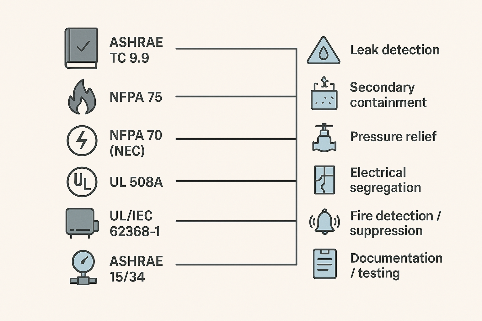
Standards and Compliance for Data Center Liquid Cooling Safety
Key Takeaway: For compliance readiness, map each liquid-cooling control (relief, containment, detection, shutdown logic) to a standard, an owner, and a test record you can produce on demand.
ASHRAE guidance
For data center liquid cooling, ASHRAE is a key reference point because it provides terminology, recommended practices, and design/operation considerations that are widely used in the industry. In particular, ASHRAE technical guidance around liquid-cooled servers and facility integration helps operators standardize expectations for loop architecture, commissioning, and ongoing maintenance.
From a compliance-readiness standpoint, ASHRAE guidance typically influences:
-
How you classify and document the liquid cooling approach (direct-to-chip vs immersion)
-
What you treat as “facility side” vs “IT side” responsibilities
-
What you record during commissioning (pressure tests, flushing/cleanliness, alarm verification)
-
How you specify allowable temperature/pressure envelopes and operational interlocks
NFPA and NEC
From a practical standpoint, this is where data center liquid cooling safety intersects with building-level life safety and electrical rules—alarm routing, shutdown behavior, and equipment clearances are evaluated in the same risk frame.
NFPA standards matter because your liquid loop doesn’t exist in isolation—it lives in an environment built around electrical safety and fire protection.
At a high level:
-
NFPA 70 (NEC) shapes how you design and maintain electrical distribution, grounding/bonding, equipment clearances, and safe work practices around energized systems.
-
NFPA 75 focuses on fire protection for IT equipment areas/data centers and drives expectations for detection, suppression strategy, and emergency operations coordination.
For operators, the practical implication is that your liquid-cooling design review should include your electrical authority and fire protection engineer early. The safety controls you select (containment, segregation, shutdown logic, alarm routing) need to make sense inside the building’s broader protection concept.
UL/IEC and pressure codes
Two different compliance tracks often intersect in liquid cooling projects:
-
Product safety and control panels: Standards such as UL/IEC safety frameworks help validate that ICT equipment, control panels, and integrated systems have been engineered to manage hazards (electrical, thermal, mechanical, fire). UL describes liquid cooling safety certification in the context of hazard-based safety engineering in “Safety Certification of IT Equipment Cooling in Data Centers”.
-
Pressure and mechanical integrity: Depending on system pressures, volumes, and jurisdiction, pressure equipment codes (for example, ASME BPVC in the U.S. or PED in Europe) can drive design, inspection, and documentation expectations for pressure-containing components.
The operator value of these frameworks isn’t “paper compliance.” It’s the discipline they force: credible failure modes, defined safety functions, and evidence that protections are designed and tested.
Engineering Controls
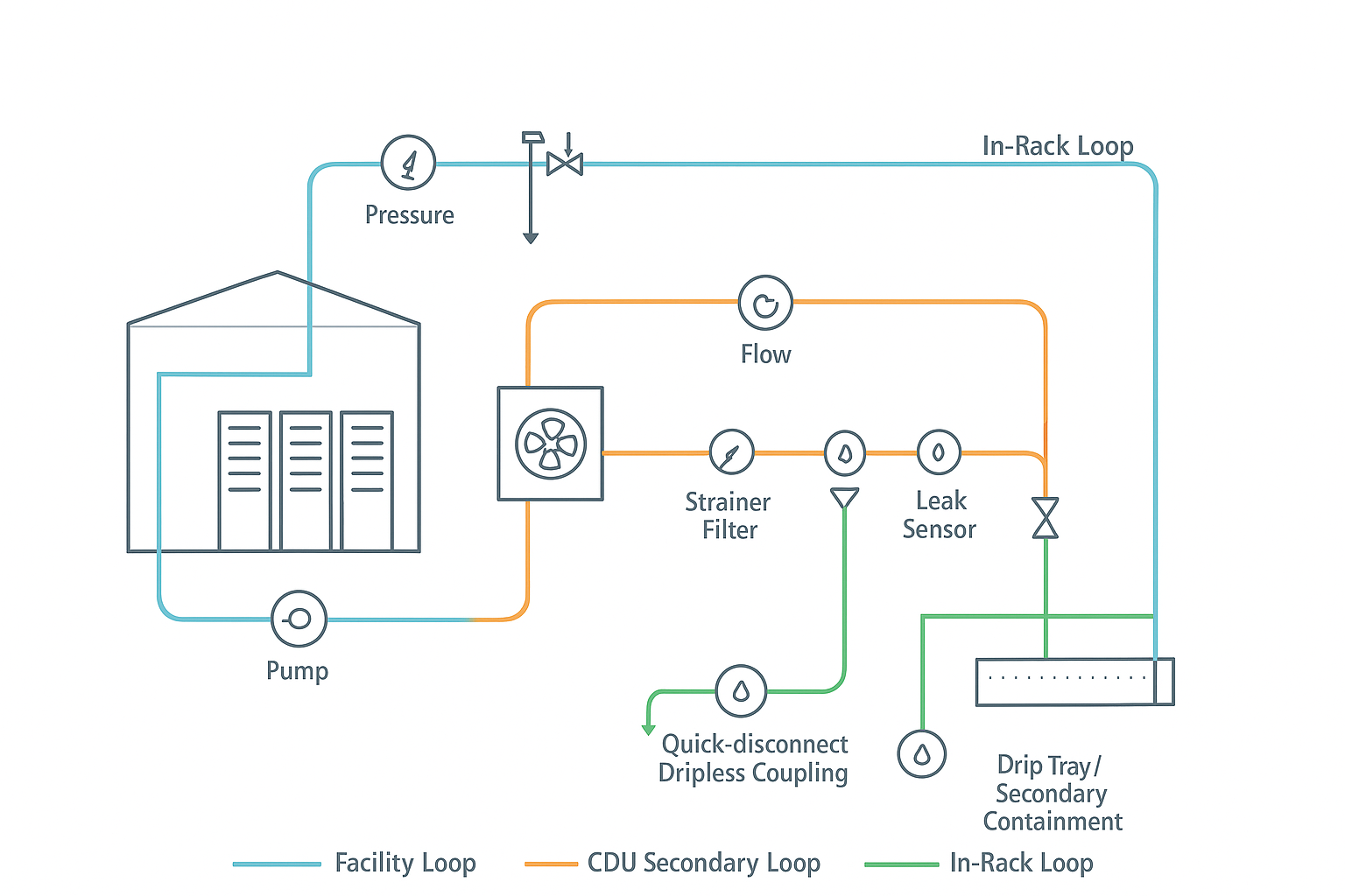
Loop design and relief
The best safety outcomes come from designing the loop so that failures are bounded: limit how much fluid can escape, how fast it can escape, and how much pressure energy can be released.
Core design patterns that consistently reduce risk:
-
Segment the system: Treat the facility loop, CDU secondary loop, and in-rack loop as separate zones with isolation boundaries. Segmentation makes shutdowns smaller and faster.
-
Design for “safe isolation”: Any section that can be isolated should still have a way to relieve thermal expansion (or otherwise prevent trapped-volume overpressure).
-
Dual relief philosophy: Use the right relief device for the scenario (e.g., pump deadhead vs trapped thermal expansion) and route discharge to a safe location with secondary containment.
-
Limit pressure at the edge: The closer you get to IT, the more you want to limit maximum allowable pressure and stored energy.
-
Fail-safe valve behavior: Know what happens on loss of power or loss of control signal. A “closed on power loss” valve can be safe in one scenario and hazardous in another if it traps volume.
Verification is part of the control. A relief device that isn’t tested, documented, and maintained is a false sense of safety.
-
Coolnet integration note: Integrated cooling + power solutions (e.g., CDU, monitoring, and control panels) can simplify interlocks, alarm routing, and compliance documentation by standardizing safety functions across deployments.
Fluids, materials, chemistry
A loop can be mechanically perfect and still fail early if the fluid program is weak. Chemistry and compatibility issues often show up as:
-
O-ring swelling/shrinkage and gasket degradation
-
Corrosion products that foul cold plates, filters, and heat exchangers
-
Particulate that damages pump seals or blocks microchannels
-
Changes in conductivity that defeat assumptions about electrical risk
Practical controls that work in the field:
-
Material compatibility matrix: Maintain a documented compatibility list for metals, elastomers, plastics, adhesives, and coatings in contact with your chosen fluid.
-
Filtration strategy: Use staged filtration appropriate to your loop (facility side vs secondary vs in-rack) and record differential pressure trends to spot plugging.
-
Fluid quality spec: Define acceptable ranges for conductivity (if applicable), pH, glycol concentration, inhibitor levels, and particulate counts—and define what triggers corrective action.
-
Sampling + labeling: Make sampling points safe and obvious; label fluid type clearly at CDUs and service points to prevent “wrong fluid” events.
-
Contamination control during service: Treat hose changes, quick-disconnect operations, and component swaps as contamination risks—use capped connections, clean work surfaces, and controlled fill/bleed procedures.
If you’re using direct-to-chip cooling, it’s common to see treated water or water/glycol on the facility/secondary side; if you’re using immersion, you need a clear plan for fluid handling, spill response, and vapor management aligned with the fluid’s safety data.
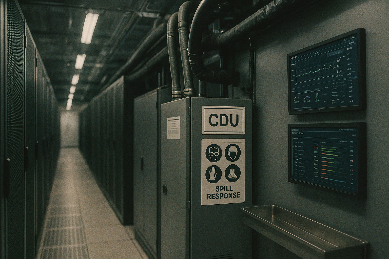
Quick‑disconnects and containment
Quick-disconnects (QDs) are where human factors meet mechanical reality. Many “leak incidents” are not design failures—they’re handling failures.
Controls that reduce QD-related leak and spray risk:
-
Use dripless couplings where practical: Design the coupling strategy to minimize trapped droplets during disconnect.
-
Standardize coupling types: Too many coupling variants increases mis-mating risk and training burden.
-
Add physical access discipline: If a coupling is hard to see or reach, it’s hard to confirm it’s fully seated.
-
Containment at likely leak points: Place drip trays and secondary containment below CDUs, manifolds, and coupling clusters. Treat gravity as a control you can design for.
-
Service-mode logic: Where available, use a controlled “service mode” that reduces pressure, isolates the correct branch, and confirms a safe state before disconnect.
Warning: The most dangerous “small leak” is the one that becomes a pressurized spray because a coupling is opened without pressure being reduced and verified.
Detection and Suppression
Leak and hydrocarbon sensors
Detection isn’t one device—it’s a coverage strategy. The right sensor choice depends on the fluid and the failure mode.
Common detection layers:
-
Leak detection cable (moisture cable): Useful under raised floors, in containment trays, and along pipe runs where drips will accumulate.
-
Point moisture sensors: Good for known drip points (below CDUs, manifolds, and connection panels).
-
Conductivity-based sensors: Relevant when fluids are expected to be conductive (or can become conductive with contamination).
-
Hydrocarbon/VOC sensors: More relevant when dealing with certain dielectric fluids, mists, or vapors where “wetness” detection isn’t sufficient.
Placement guidance operators tend to miss:
-
Put sensors where fluid will go, not where piping happens to be. That usually means low points, containment sumps, and drip trays.
-
Use detection to differentiate “seep” vs “spray” by combining signals (e.g., pressure drop + leak cable alarm) to improve data center leak detection accuracy.
-
Validate detection during commissioning with a documented test method. A sensor that never gets tested will eventually become a dashboard decoration.
Interlocks and shutdowns
Interlocks are where safety and uptime trade off. The goal isn’t “trip on any alarm.” The goal is to stop escalation while minimizing unnecessary outages.
A practical shutdown hierarchy:
-
Alert-only tier (seep): Alarm → ticket → operator inspection window.
-
Controlled isolation tier (drip): Alarm + confirmatory signal (pressure/flow anomaly) → isolate a branch → keep the rest of the loop running.
-
Rapid shutdown tier (spray/rupture): Multiple signals (fast pressure drop, high-rate leak detection, cabinet moisture) → pump stop + isolation + power-safe actions per your electrical safety plan.
Two implementation principles help:
-
Make interlocks inspectable: Operators should be able to see what condition caused a shutdown and how to reset safely.
-
Tie interlocks to SOPs: A shutdown without a clear, rehearsed response path leads to unsafe improvisation.
Coolnet notes that liquid-cooling platforms may support optional leak detection kits and PLC-based monitoring; regardless of vendor, treat the interlock logic as a safety function that must be documented, tested, and maintained.
This is also where a CDU pressure relief and isolation strategy becomes operational rather than theoretical: your alarms should map cleanly to “inspect,” “isolate,” or “shutdown,” with no ambiguous middle state.
Fire detection and agents
Fire risk in liquid-cooled environments is still dominated by the usual suspects: power distribution faults, battery systems, cabling, and electronic failures. Liquid cooling changes two things:
-
It can introduce additional fuels or vapor risks depending on the fluid.
-
It can change airflow patterns and compartmentalization assumptions in the rack/row.
Operator controls to focus on:
-
Detection strategy: Align smoke/air sampling where used, plus point detection, to the actual airflow and enclosure design.
-
Suppression strategy: Ensure your selected agent and discharge plan fits the room tightness, ventilation behavior, and equipment sensitivity.
-
Coordination with shutdown logic: Decide how fire signals interact with pump shutdown, electrical shutdown, and EPO policies.
The right answer varies by facility, but the operator obligation is consistent: make sure fire protection, electrical safety, and liquid-loop safety are not three separate systems with three separate alarm philosophies.
Operations and Training
Commissioning and SOPs
Commissioning is where safety is either proven—or assumed. For liquid cooling, treat commissioning as a structured set of verifications, not a single “pressure test passed.”
Commissioning items that materially reduce incidents:
-
Pressure testing with documented hold times for each segmented zone
-
Functional tests of relief paths (including discharge routing and containment)
-
Leak detection functional tests (sensor response + alarm routing)
-
Interlock tests for each tier of response (alert, isolate, shutdown)
-
Flow verification and balancing to confirm expected ΔP and avoid hidden deadhead conditions
-
Labeling verification (fluid type, isolation boundaries, service points, emergency actions)
SOPs should include:
-
“Service mode” steps (pressure reduction, isolation, verification)
-
Fill/bleed procedures and contamination controls
-
A clear escalation path for alarms (who owns what: facilities, IT, EHS)
Maintenance and PM
Preventive maintenance (PM) is not just “keep it running.” It’s how you keep safety controls credible over time.
PM that tends to pay back:
-
Relief device inspection and testing per manufacturer guidance and site policy
-
Filter and strainer PM based on differential pressure trends
-
Pump condition monitoring (seal health, vibration where applicable, redundancy switchover tests)
-
Sensor calibration checks (leak cable integrity, point sensor function, hydrocarbon sensor calibration)
-
Hose/coupling inspection cadence with defined replacement intervals for wear items
Where operators get burned is “invisible drift”: chemistry shifts, seals age, fittings loosen, and alarm thresholds don’t get revisited after the first deployment. Close that loop with trend reviews in your maintenance program.
HazCom, PPE, and drills
Even “low hazard” fluids create risk when they’re pressurized, hot, or in confined spaces.
Minimum training and readiness elements:
-
HazCom alignment: Keep current SDS access paths, spill classifications, and reporting requirements.
-
PPE guidance: Define PPE for normal service, spill response, and spray/rupture events. Make it available where work happens.
-
Drills: Run short, realistic drills: “leak cable alarm under row 3,” “CDU pressure alarm,” “spray event with adjacent energized gear.”
-
Post-incident learning: After any leak event (even minor), run a blameless review to identify whether the failure was design, maintenance, training, or detection.
A strong program makes the first 10 minutes of an incident predictable, not improvised.
Metrics and Outcomes
Uptime and incident rate
If you want safety investment to survive budget cycles, you need measurable outcomes.
Useful operator metrics:
-
Leak events per quarter (by severity class: seep/drip/spray)
-
Mean time to detect (MTTD) and mean time to isolate (MTTI)
-
Unplanned shutdowns caused by liquid alarms (a measure of interlock tuning quality)
-
Repeat incidents on the same component type or location (signals systemic design/training issues)
A mature program will see a shift from “found by humans” to “found by sensors,” and from “whole-loop shutdowns” to “segmented isolation.”
PUE/WUE and energy impact
Operators often adopt liquid cooling for capacity and efficiency. Safety controls should not be treated as the enemy of efficiency.
What to track:
-
Pump power vs delivered cooling (efficiency of hydraulic design)
-
Supply/return temperatures and approach temps (evidence that the loop is operating as designed)
-
Water usage impacts (especially where adiabatic systems or facility heat rejection changes)
The safety angle: stable hydraulics and clean fluids usually improve both reliability and efficiency. Overpressure events, plugged filters, and chemistry problems are not just safety risks—they’re performance degraders.
Audit and documentation
Compliance readiness is documentation readiness. Auditors, insurers, and internal risk committees tend to ask the same questions:
-
What standards/guidance did you design against?
-
What are your safety functions (relief, containment, detection, interlocks), and how do you test them?
-
Where is your evidence (commissioning reports, maintenance records, calibration logs, training records)?
-
What changed since last review (MOC/change management)?
If you want a simple operator rule: every control should have an owner, a test method, and a record. Without that, you don’t have a control—you have an assumption.
For operators building an internal knowledge base, Coolnet’s liquid cooling resources—such as its overview of Liquid Cooling and its explanation of CDU fundamentals—can help standardize terminology across facilities and IT teams.
Conclusion
AI/HPC density doesn’t have to force a trade between performance and safety. The operators who succeed with liquid cooling are the ones who treat it as a system with credible failure modes—and design controls that keep those failures bounded.
Standards alignment helps you speak the language of auditors, AHJs, and insurers, but the real value is operational: fewer outages, smaller blast radius when something goes wrong, and faster recovery.
Next steps are pragmatic:
-
Assess your current gaps against the risk landscape (fluid, leak/spray, overpressure).
-
Prioritize engineering controls that reduce blast radius first (segmentation, relief, containment).
-
Validate detection and interlocks with commissioning-grade tests.
-
Train teams and rehearse response so incidents don’t become improvisation.
If you’re preparing for expansion, it’s worth bookmarking a short internal checklist for liquid cooling compliance readiness—including your SOPs, test records, and maintenance evidence—so safety keeps pace with density.


 IPv6 network supported